- 您现在的位置:买卖IC网 > Sheet目录868 > LTM4605EV#PBF (Linear Technology)IC DC/DC UMODULE 5A 141-LGA
�� �
�
�LTM4605�
�APPLICATIONS� INFORMATION�
�To� set� the� output� voltage� at� 12V,� the� resistor� R� FB� from� V� FB�
�pin� to� ground� should� be� chosen� as:�
�Consider� the� safety� margin� about� 30%,� we� can� choose�
�the� sensing� resistor� as� 8m� Ω� .�
�R� FB� =�
�0.8V ? 100k�
�V� OUT� ?� 0.8V�
�≈� 7.15k�
�For� the� input� capacitor,� use� a� low� ESR� sized� capacitor� to�
�handle� the� maximum� RMS� current.� Input� capacitors� are�
�required� to� be� placed� adjacent� to� the� module.� In� Figure� 14,�
�To� choose� a� proper� inductor,� we� need� to� know� the� current�
�ripples� at� different� input� voltages.� The� inductor� should�
�be� chosen� by� considering� the� worst� case� in� the� practi-�
�cal� operating� region.� If� the� maximum� output� power� P� is�
�150W� at� buck� mode,� we� can� get� the� current� ripple� ratio�
�of� the� current� ripple� Δ� I� L� to� the� maximum� inductor� current�
�I� L� as� follows:�
�the� 10μF� ceramic� input� capacitors� are� selected� for� their�
�ability� to� handle� the� large� RMS� current� into� the� converter.�
�The� 100μF� bulk� capacitor� is� only� needed� if� the� input� source�
�impedance� is� compromised� by� long� inductive� leads� or�
�traces.�
�For� the� output� capacitor,� the� output� voltage� ripple� and�
�transient� requirements� require� low� ESR� capacitors.� If�
�(V� IN� –� V� OUT� )� ?� V� OUT�
�ΔI� L�
�I� L�
�=�
�V� IN� ?� L� ?� f� ?� P�
�2�
�assuming� that� the� ESR� dominates� the� output� ripple,� the�
�output� ripple� is� as� follows:�
�Δ� V� OUT(P-P)� =� ESR� ?� Δ� I� L�
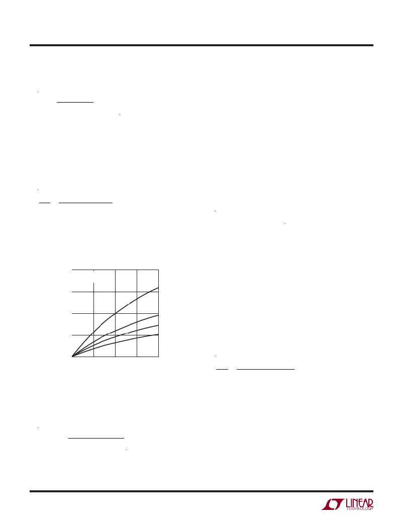
�Figure� 3� shows� the� current� ripple� ratio� at� different� input�
�voltages� based� on� the� inductor� values:� 1.5μH,� 2.5μH,�
�3.3μH� and� 4.7μH.� If� we� need� 30%� ripple� current� ratio� at�
�all� inputs,� the� 3.3μH� inductor� can� be� selected.�
�If� a� total� low� ESR� of� about� 5m� Ω� is� chosen� for� output�
�capacitors,� the� maximum� output� ripple� of� 17.5mV� occurs�
�at� the� input� voltage� of� 20V� with� the� current� ripple� at� 3.5A.�
�0.8�
�0.6�
�V� OUT� =� 12V�
�?� =� 400kHz�
�1.5μH�
�Boost� Mode� Operation�
�For� boost� mode� operation,� use� input� voltage� V� IN� =� 5V� to�
�12V,� V� OUT� =� 12V� and� f� =� 400kHz.�
�0.4�
�2.5μH�
�Set� the� PLLFLTR� pin� and� R� FB� as� in� buck� mode.�
�If� the� maximum� output� power� P� is� 60W� at� boost� mode�
�0.2�
�3.3μH�
�4.7μH�
�and� the� module� ef?ciency� η� is� about� 95%,� we� can� get�
�the� current� ripple� ratio� of� the� current� ripple� Δ� I� L� to� the�
�maximum� inductor� current� I� L� as� follows:�
�0�
�12� 14� 16� 18� 20�
�INPUT� VOLTAGE� V� IN� (V)�
�4605� F03�
�Figure� 3.� Current� Ripple� Ratio� at� Different� Inputs� for� Buck� Mode�
�Δ� I� L�
�I� L�
�=�
�(V� OUT� ?� V� IN� ) ? V� IN2� η�
�V� OUT� ?� L� ?� f� ?� P�
�Figure� 4.� shows� the� current� ripple� ratio� at� different� input�
�At� buck� mode,� sensing� resistor� selection� is� based� on�
�the� maximum� output� current� and� the� allowed� maximum�
�sensing� threshold� 130mV.�
�voltages� based� on� the� inductor� values:� 1.5μH,� 2.5μH,�
�3.3μH� and� 4.7μH.� If� we� need� 30%� ripple� current� ratio� at�
�all� inputs,� the� 3.3μH� inductor� can� be� selected.�
�R� SENSE� =�
�2� ?� 130mV�
�2� ?� (P� /� V� OUT� )� ?� Δ� I� L�
�4605fc�
�14�
�发布紧急采购,3分钟左右您将得到回复。
相关PDF资料
LTM4606MPV#PBF
IC DC/DC UMODULE 6A 133-LGA
LTM4607IV#PBF
IC BUCK/BOOST SYNC ADJ 5A 141LGA
LTM4608AEV#PBF
IC BUCK SYNC ADJ 8A 68LGA
LTM4608IV#PBF
IC DC/DC UMODULE 8A 68-LGA
LTM4609IV#PBF
IC BUCK/BOOST SYNC ADJ 4A 141LGA
LTM4612IV#PBF
IC BUCK SYNC ADJ 5A 133LGA
LTM4613MPV#PBF
IC UMODULE DC/DC 8A 133-LGA
LTM4614IV#PBF
IC UMODULE DC/DC DUAL 4A 144LGA
相关代理商/技术参数
LTM4605EV#PBF
制造商:Linear Technology 功能描述:IC SMPS CONTROLLER CURRENT-MODE LGA
LTM4605EVPBF
制造商:Linear Technology 功能描述:Conv DC-DC Step Up Step Down
LTM4605EV-PBF
制造商:LINER 制造商全称:Linear Technology 功能描述:High Effi ciency Buck-Boost DC/DC μModule
LTM4605IV#PBF
功能描述:IC DC/DC UMODULE 5A 141-LGA RoHS:是 类别:电源 - 板载 >> DC DC Converters 系列:µModule® 设计资源:VI-200, VI-J00 Design Guide, Appl Manual 标准包装:1 系列:* 类型:隔离 输出数:1 电压 - 输入(最小):21V 电压 - 输入(最大):32V Voltage - Output 1:5V Voltage - Output 2:- Voltage - Output 3:- 电流 - 输出(最大):* 电源(瓦) - 制造商系列:100W 电压 - 隔离:* 特点:* 安装类型:通孔 封装/外壳:9-SlimMod 尺寸/尺寸:4.60" L x 1.80" W x 0.52" H(116.8mm x 45.7mm x 13.2mm) 包装:散装 工作温度:-25°C ~ 85°C 效率:* 电源(瓦特)- 最大:*
LTM4605IV#PBF
制造商:Linear Technology 功能描述:DC/DC MICRO MODULE IC
LTM4605IVPBF
制造商:Linear Technology 功能描述:Conv DC-DC Step Up Step Down
LTM4605IV-PBF
制造商:LINER 制造商全称:Linear Technology 功能描述:High Effi ciency Buck-Boost DC/DC μModule
LTM4605RD
功能描述:LED 电路板指示器 Vert LED Assmbly 5mm Red RoHS:否 制造商:Lumex LED 大小:3 mm 照明颜色:Green 波长:565 nm 光强度:30 mcd 安装类型:SMD/SMT 显示角:60 deg 封装:Reel